
电动机功率因数
不同负载和额定功率下电动机功率因数的参考数据。
概述
交流电机的功率因数 (PF) 是有功功率(瓦特)与视在功率(伏安)之比。低功率因数意味着供电必须输送比产生相同有用功所需更多的电流,从而增加电缆、变压器和开关设备的损失。电机是工业厂区低功率因数的主要来源,因为它们消耗励磁(无功)电流来维持磁场。
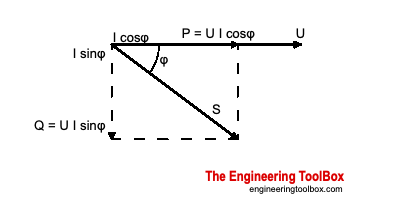
功率因数表示为 cos φ,其中 φ 为电压和电流波形之间的相位角。纯电阻负载的 PF = 1.0;典型感应电机从空载的 0.15 到满载的 0.85–0.91 不等,取决于尺寸。
超前和滞后功率因数
感应电机通常以滞后功率因数运行,因为其励磁电流滞后于施加的电压。电容器组或过励同步电机可以本地提供无功功率,如果修正量大于负载所需,可能产生超前功率因数。超前和滞后情况具有相同的数值功率因数定义,但无功功率的符号和 VAR 流动方向不同。
关键公式
单相功率因数
有功、无功和视在功率
其中 S 为视在功率 (VA),P 为有功功率 (W),Q 为无功功率 (VAR)。
三相电机功率
低功率因数的电流倍数
功率因数降低的电路必须承载成比例更多的电流:
例如,在 PF = 0.7 时,电流是单位功率因数下电流的 1/0.7 ≈ 1.43 倍。
变量
| 符号 | 说明 | 单位 |
|---|---|---|
| PF | 功率因数 | 无量纲 |
| P | 有功功率 | W |
| S | 视在功率 | VA |
| Q | 无功功率 | VAR |
| V | 电压 | V |
| V_L | 线间电压 | V |
| I_L | 线电流 | A |
| φ | V 与 I 之间的相位角 | 度 |
典型电机功率因数
Power factor varies strongly with load and motor rating. Values below are for standard 1800 rpm NEMA motors:
电机 功率 (hp) | No 载荷 | 25 % 载荷 | 50 % 载荷 | 75 % 载荷 | Full 载荷 |
|---|---|---|---|---|---|
| 0–5 | 0.15–0.20 | 0.50–0.60 | 0.72 | 0.82 | 0.84 |
| 5–20 | 0.15–0.20 | 0.50–0.60 | 0.74 | 0.84 | 0.86 |
| 20–100 | 0.15–0.20 | 0.50–0.60 | 0.79 | 0.86 | 0.89 |
| 100–300 | 0.15–0.20 | 0.50–0.60 | 0.81 | 0.88 | 0.91 |
来源: engineeringtoolbox.com
Wire Cross-Section Multiplier
When power factor drops, conductors must be oversized to carry the additional current. The table below gives the required cross-section multiplier relative to a unity-power-factor design:
功率 系数 | |
|---|---|
| 1 | 1 |
| 0.9 | 1.23 |
| 0.8 | 1.56 |
| 0.7 | 2.04 |
| 0.6 | 2.78 |
| 0.5 | 4 |
| 0.4 | 6.25 |
来源: engineeringtoolbox.com
Industry Typical Power Factors
| Office | 0.8 | 0.9 |
| Hospital | 0.75 | 0.8 |
| Brewery | 0.75 | 0.8 |
| Cement | 0.75 | 0.8 |
| Foundry | 0.75 | 0.8 |
| Plastic production | 0.75 | 0.8 |
| Forging | 0.7 | 0.8 |
| Steel works | 0.65 | 0.8 |
| Mine (coal) | 0.65 | 0.8 |
| Chemical | 0.65 | 0.75 |
| Metalworking | 0.65 | 0.7 |
| Manufacturing (machines) | 0.6 | 0.65 |
| Stamping | 0.6 | 0.7 |
| Oil pumping | 0.4 | 0.6 |
| Textiles | 0.35 | 0.6 |
来源: engineeringtoolbox.com
Power Factor vs. Motor Load
The chart below shows how power factor improves as motor load increases. Partial loading is the primary cause of poor power factor in motor fleets.
功率 系数 vs. 电机 载荷
计算器
Use this calculator to find apparent power and reactive power from measured active power and power factor.
电机 Apparent and Reactive 功率
Interactive Power Factor Correction Chart
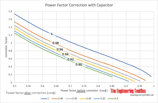
The original capacitor correction chart is represented below as selectable data. The factor is multiplied by active power in kW to estimate required capacitor size in kVAR.
电容器 Correction 系数 by Initial and Target 功率 系数
功率 系数 Correction 电容器 Size
还原的原始源表
以下表格还原自原始来源页面,以保留完整的参考数据。
Electrical Motors - Typical Power Factors
功率 (马力) | 速度 (rpm) | 功率 系数 (cos φ ) | 功率 系数 (cos φ ) | 功率 系数 (cos φ ) | 功率 系数 (cos φ ) | 功率 系数 (cos φ ) |
|---|---|---|---|---|---|---|
| Unloaded | 1/4 load | 1/2 load | 3/4 load | full load | — | — |
| 0 - 5 | 1800 | 0.15 - 0.20 | 0.5 - 0.6 | 0.72 | 0.82 | 0.84 |
| 5 - 20 | 1800 | 0.15 - 0.20 | 0.5 - 0.6 | 0.74 | 0.84 | 0.86 |
| 20 - 100 | 1800 | 0.15 - 0.20 | 0.5 - 0.6 | 0.79 | 0.86 | 0.89 |
| 100 - 300 | 1800 | 0.15 - 0.20 | 0.5 - 0.6 | 0.81 | 0.88 | 0.91 |
来源: engineeringtoolbox.com
Electrical Motors - Power Factors by Industry
功率 系数 | |
|---|---|
| Brewery | 75 - 80 |
| Cement | 75 - 80 |
| Chemical | 65 - 75 |
| Electro-chemical | 65 - 75 |
| Foundry | 75 - 80 |
| Forging | 70 - 80 |
| Hospital | 75 - 80 |
| Manufacturing, machines | 60 - 65 |
| Manufacturing, paint | 65 - 70 |
| Metalworking | 65 - 70 |
| Mine, coal | 65 - 80 |
| Office | 80 - 90 |
| Oil pumping | 40 - 60 |
| Plastic production | 75 - 80 |
| Stamping | 60 - 70 |
| Steel works | 65 - 80 |
| Textiles | 35 - 60 |
来源: engineeringtoolbox.com
Electrical Motors - Power Factor Correction with Capacitor
功率因数 after improvement (cosΦ) | 功率因数 after improvement (cosΦ) | 功率因数 after improvement (cosΦ) | 功率因数 after improvement (cosΦ) | 功率因数 after improvement (cosΦ) | 功率因数 after improvement (cosΦ) | 功率因数 after improvement (cosΦ) | 功率因数 after improvement (cosΦ) | 功率因数 after improvement (cosΦ) | 功率因数 after improvement (cosΦ) | 功率因数 after improvement (cosΦ) | 电容器 correction factor |
|---|---|---|---|---|---|---|---|---|---|---|---|
| 1 | 0.99 | 0.98 | 0.97 | 0.96 | 0.95 | 0.94 | 0.93 | 0.92 | 0.91 | 0.9 | — |
| 0.5 | 1.73 | 1.59 | 1.53 | 1.48 | 1.44 | 1.4 | 1.37 | 1.34 | 1.3 | 1.28 | 1.25 |
| 0.55 | 1.52 | 1.38 | 1.32 | 1.28 | 1.23 | 1.19 | 1.16 | 1.12 | 1.09 | 1.06 | 1.04 |
| 0.6 | 1.33 | 1.19 | 1.13 | 1.08 | 1.04 | 1.01 | 0.97 | 0.94 | 0.91 | 0.88 | 0.85 |
| 0.65 | 1.17 | 1.03 | 0.97 | 0.92 | 0.88 | 0.84 | 0.81 | 0.77 | 0.74 | 0.71 | 0.69 |
| 0.7 | 1.02 | 0.88 | 0.81 | 0.77 | 0.73 | 0.69 | 0.66 | 0.62 | 0.59 | 0.56 | 0.54 |
| 0.75 | 0.88 | 0.74 | 0.67 | 0.63 | 0.58 | 0.55 | 0.52 | 0.49 | 0.45 | 0.43 | 0.4 |
| 0.8 | 0.75 | 0.61 | 0.54 | 0.5 | 0.46 | 0.42 | 0.39 | 0.35 | 0.32 | 0.29 | 0.27 |
| 0.85 | 0.62 | 0.48 | 0.42 | 0.37 | 0.33 | 0.29 | 0.26 | 0.22 | 0.19 | 0.16 | 0.14 |
| 0.9 | 0.48 | 0.34 | 0.28 | 0.23 | 0.19 | 0.16 | 0.12 | 0.09 | 0.06 | 0.02 | — |
| 0.91 | 0.45 | 0.31 | 0.25 | 0.21 | 0.16 | 0.13 | 0.09 | 0.06 | 0.02 | — | — |
| 0.92 | 0.43 | 0.28 | 0.22 | 0.18 | 0.13 | 0.1 | 0.06 | 0.03 | — | — | — |
| 0.93 | 0.4 | 0.25 | 0.19 | 0.15 | 0.1 | 0.07 | 0.03 | — | — | — | — |
| 0.94 | 0.36 | 0.22 | 0.16 | 0.11 | 0.07 | 0.04 | — | — | — | — | — |
| 0.95 | 0.33 | 0.18 | 0.12 | 0.08 | 0.04 | — | — | — | — | — | — |
| 0.96 | 0.29 | 0.15 | 0.09 | 0.04 | — | — | — | — | — | — | — |
| 0.97 | 0.25 | 0.11 | 0.05 | — | — | — | — | — | — | — | — |
| 0.98 | 0.2 | 0.06 | — | — | — | — | — | — | — | — | — |
| 0.99 | 0.14 | — | — | — | — | — | — | — | — | — | — |
来源: engineeringtoolbox.com
Induction Motors - KVAR Correction Units
Induction 电机 Rating (HP) | Nominal 电机 速度 (rpm) | Nominal 电机 速度 (rpm) | Nominal 电机 速度 (rpm) | Nominal 电机 速度 (rpm) | Nominal 电机 速度 (rpm) | Nominal 电机 速度 (rpm) |
|---|---|---|---|---|---|---|
| 3600 | 3600 | 1800 | 1800 | 1200 | 1200 | — |
| Capacitor Rating (KVAR) | Reduction of Line Current (%) | Capacitor Rating (KVAR) | Reduction of Line Current (%) | Capacitor Rating (KVAR) | Reduction of Line Current (%) | — |
| 3 | 1.5 | 14 | 1.5 | 23 | 2.5 | 28 |
| 5 | 2 | 14 | 2.5 | 22 | 3 | 26 |
| 7.5 | 2.5 | 14 | 3 | 20 | 4 | 21 |
| 10 | 4 | 14 | 4 | 18 | 5 | 21 |
| 15 | 5 | 12 | 5 | 18 | 6 | 20 |
| 20 | 6 | 12 | 6 | 17 | 7.5 | 19 |
| 25 | 7.5 | 12 | 7.5 | 17 | 8 | 19 |
| 30 | 8 | 11 | 8 | 16 | 10 | 19 |
| 40 | 12 | 12 | 13 | 15 | 16 | 19 |
| 50 | 15 | 12 | 18 | 15 | 20 | 19 |
| 60 | 18 | 12 | 21 | 14 | 22.5 | 17 |
| 75 | 20 | 12 | 23 | 14 | 25 | 15 |
| 100 | 22.5 | 11 | 30 | 14 | 30 | 12 |
| 125 | 25 | 10 | 36 | 12 | 35 | 12 |
| 150 | 30 | 10 | 42 | 12 | 40 | 12 |
| 200 | 35 | 10 | 50 | 11 | 50 | 10 |
| 250 | 40 | 11 | 60 | 10 | 62.5 | 10 |
| 300 | 45 | 11 | 68 | 10 | 75 | 12 |
| 350 | 50 | 12 | 75 | 8 | 90 | 12 |
| 400 | 75 | 10 | 80 | 8 | 100 | 12 |
| 450 | 80 | 8 | 90 | 8 | 120 | 10 |
| 500 | 100 | 8 | 120 | 9 | 150 | 12 |
来源: engineeringtoolbox.com
原始源图
以下原始来源图像予以保留,以免丢失视觉参考资料。当图像包含图表或表格数据时,其提取值已呈现在页面的表格、计算器或交互式图表中;其余图像保留为视觉来源参考。
工程要点
- Oversizing penalties. A plant at PF = 0.7 needs transformers, cables, and switchgear rated 43 % higher (1/0.7) than the same real load at unity power factor.
- Utility surcharges. Most utilities penalize commercial customers below PF ≈ 0.90–0.95. Correcting power factor can eliminate demand charges and reduce monthly bills.
- Capacitor correction. Power factor correction capacitors supply reactive current locally, reducing the current drawn from the supply. Capacitors should be switched with the motor or grouped at the bus. Over-correction (leading PF) can cause voltage rise and resonance.
- Standards. IEC 61000-3-2 limits harmonic current distortion, which also affects measured power factor. Variable-frequency drives produce harmonic-rich current and may require line reactors or passive filters in addition to power-factor capacitors.
- Motor loading. Running motors well below rated load is the most common cause of poor plant power factor. Matching motor size to the driven load, or using adjustable-speed drives, directly improves PF.
- Synchronous motors. An over-excited synchronous motor can be used to correct power factor and is sometimes preferred in large plants because it provides leading VARs without separate capacitor banks.