
風管摩擦壓降
風管內空氣流動產生的摩擦壓降計算與參考資料。
概述
Duct friction pressure loss (major loss) is the energy drop caused by air flowing through ductwork. In galvanized steel circular ducts with turbulent flow, the loss per unit length depends on airflow rate and duct diameter. This page covers the standard empirical formula, reference data for common duct sizes, and practical design limits.
關键公式
Duct Friction Loss (Imperial)
where is in inches of water gauge per 100 ft of duct, is airflow in cfm, and is duct inside diameter in inches.
Air Velocity from Flow Rate
For a circular duct with diameter in inches and flow in cfm, velocity in ft/min is:
Rectangular Duct Equivalent Diameter
For non-circular ducts, replace with the equivalent diameter:
where and are side dimensions in inches.
變量
| 符號 | 說明 | Typical Unit |
|---|---|---|
| Head loss (friction) | in H₂O / 100 ft | |
| Air volume flow rate | cfm | |
| Duct inside diameter | in | |
| Air velocity | ft/min | |
| Rectangular duct sides | in | |
| Equivalent diameter | in |
Friction Loss Reference Data
Head loss and air velocity for galvanized steel circular ducts with turbulent airflow.
空氣 體積 (cfm) | 风管 Size (in) | 扬程 Loss (inH₂O/100ft) | 空氣 速度 (ft/min) |
|---|---|---|---|
| 100 | 4 | 0.65 | 1146 |
| 100 | 6 | 0.09 | 509 |
| 100 | 8 | 0.02 | 286 |
| 200 | 5 | 0.8 | 1467 |
| 200 | 8 | 0.08 | 573 |
| 200 | 10 | 0.02 | 367 |
| 400 | 6 | 1.19 | 2037 |
| 400 | 8 | 0.28 | 1146 |
| 400 | 12 | 0.04 | 509 |
| 800 | 10 | 0.34 | 1467 |
| 800 | 12 | 0.14 | 1019 |
| 800 | 16 | 0.03 | 573 |
| 1600 | 16 | 0.12 | 1146 |
來源: engineeringtoolbox.com
Air Velocity Calculator
Estimate air velocity in a circular duct from flow rate and duct size.
风管 空氣 速度
Imperial Units Calculator
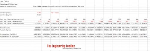
The original page included an Imperial units calculator. This migrated version calculates air velocity, straight-duct friction loss per 100 ft, and total friction loss for round galvanized steel duct using the source equation.
空氣 风管 摩擦 Loss - 英制 單位s
SI Units Calculator
This SI calculator is the same equation with metric inputs converted internally to cfm and inches.
空氣 风管 摩擦 Loss - SI 單位s
單位換算器
风管 空氣flow and 壓力 單位 转換器
Friction Loss Trend — 10 in Duct
The chart below shows how friction loss rises sharply with airflow in a 10-inch duct. Loss scales roughly with , so doubling airflow roughly quadruples the pressure drop.
摩擦 Loss vs 空氣 體積 — 10 in 风管
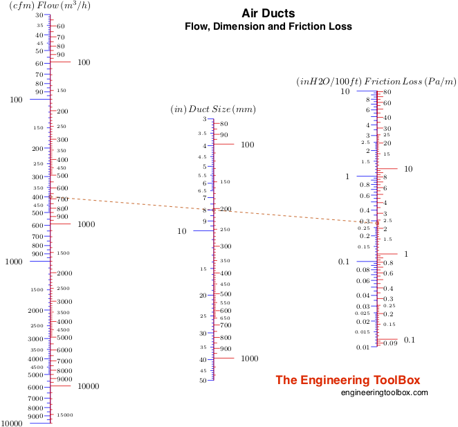
Air Ducts - Friction Loss Diagram
The original friction loss diagram covers several round duct sizes. This interactive version keeps the same intent by plotting friction loss against air volume for common duct diameters.
空氣 风管s - 摩擦 Loss 圖
还原的原始源表
The following tables are restored from the original source page to preserve the complete reference data.
Air Ducts - Major Friction Head Loss
风管 Size (inches) | 风管 Size (inches) | 风管 Size (inches) | 风管 Size (inches) | 风管 Size (inches) | 风管 Size (inches) | 风管 Size (inches) | 扬程 Loss (inches water gauge per 100 feet duct) |
|---|---|---|---|---|---|---|---|
| 4 | 5 | 6 | 8 | 10 | 12 | 16 | — |
| 100 | 0.65 | 0.21 | 0.09 | 0.02 | 0.01 | — | — |
| 1146 | 733 | 509 | 286 | 183 | — | — | — |
| 200 | — | 0.8 | 0.32 | 0.08 | 0.02 | 0.01 | — |
| — | 1467 | 1019 | 573 | 367 | 255 | — | — |
| 400 | — | — | 1.19 | 0.28 | 0.09 | 0.04 | 0.01 |
| — | — | 2037 | 1146 | 733 | 509 | 286 | — |
| 800 | — | — | — | — | 0.34 | 0.14 | 0.03 |
| — | — | — | — | 1467 | 1019 | 573 | — |
| 1600 | — | — | — | — | — | — | 0.12 |
| — | — | — | — | — | — | 1146 | — |
來源: engineeringtoolbox.com
Air Ducts - Major Friction Head Loss, Normalized Source Rows
The source table alternates friction head-loss rows and air-velocity rows under the same duct-size columns. The normalized table below preserves the same source values in one row per air volume.
空氣 體積 (cfm) | (inH2O/100ft) | (inH2O/100ft) | (inH2O/100ft) | (inH2O/100ft) | (inH2O/100ft) | (inH2O/100ft) | (inH2O/100ft) | (ft/min) | (ft/min) | (ft/min) | (ft/min) | (ft/min) | (ft/min) | (ft/min) |
|---|---|---|---|---|---|---|---|---|---|---|---|---|---|---|
| 100 | 0.65 | 0.21 | 0.09 | 0.02 | 0.01 | — | — | 1146 | 733 | 509 | 286 | 183 | — | — |
| 200 | — | 0.8 | 0.32 | 0.08 | 0.02 | 0.01 | — | — | 1467 | 1019 | 573 | 367 | 255 | — |
| 400 | — | — | 1.19 | 0.28 | 0.09 | 0.04 | 0.01 | — | — | 2037 | 1146 | 733 | 509 | 286 |
| 800 | — | — | — | — | 0.34 | 0.14 | 0.03 | — | — | — | — | 1467 | 1019 | 573 |
| 1600 | — | — | — | — | — | — | 0.12 | — | — | — | — | — | — | 1146 |
來源: engineeringtoolbox.com
原始源圖
The following original source images are preserved to avoid losing visual reference material. When an image contains chart or tabular data, its extracted values are represented in the page tables, calculators, or interactive charts; remaining images are retained as visual source references.
工程要點
- Noise limits. Air velocity should stay below roughly 600–1000 ft/min in residential applications, 1500 ft/min in quiet commercial spaces, and 2000+ ft/min only in industrial settings. Exceeding these limits causes objectionable noise.
- Turbulent flow assumption. The empirical formula above assumes fully developed turbulent flow, which is typical for HVAC duct sizing. It does not apply to laminar or transitional regimes.
- Material. Reference data applies to galvanized steel ducts. Flex duct, lined duct, and fiberglass duct have higher friction factors and require correction.
- Fittings and transitions. The formulas cover major (straight-duct) losses only. Elbows, tees, transitions, dampers, and grilles add minor losses that often dominate in short duct runs. Total system pressure drop must include both.
- Rectangular ducts. Always convert to equivalent circular diameter before using the friction loss formula. Undersized rectangular ducts are a common source of excessive static pressure.
- Economic balance. Larger ducts reduce friction loss (and fan energy) but increase material and installation cost. The relationship means a modest increase in duct diameter yields large reductions in pressure drop.