
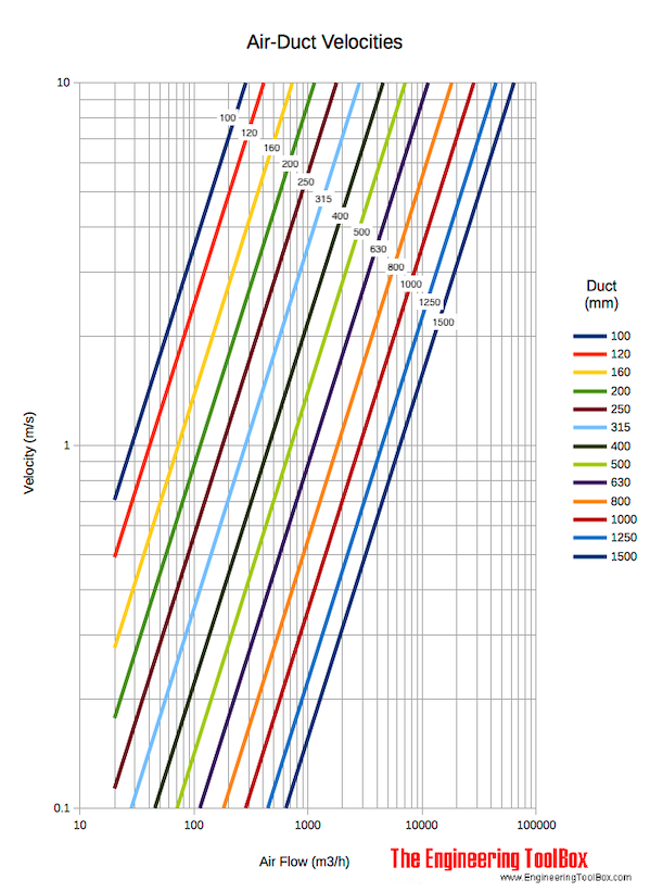
風管風速圖
風量、風管尺寸和空氣流速之間關係的參考圖與計算資料。
概述
This page provides engineering reference data for air duct velocity diagrams used in HVAC system design. The diagram relates airflow rate, duct size, and air velocity, allowing for quick estimation of key parameters. Understanding this relationship is fundamental for sizing ducts to meet airflow requirements while considering practical constraints like noise and energy efficiency.
Download and print Air Ducts Velocity Diagram with metric and Imperial units!
The velocity in a 1000 mm duct with airflow 3000 m3/h is approximately 1.1 m/s according the diagram above.
關键公式
The fundamental relationship for air velocity in a duct is derived from the continuity equation.
General Velocity Formula
For a Circular Duct
Combining the velocity formula with the area of a circle gives:
Area of a Circular Duct
變量
| 符號 | 說明 | Common Units |
|---|---|---|
| Air velocity | m/s, fpm | |
| Volumetric airflow rate | m³/h, m³/s, CFM | |
| Duct cross-sectional area | m², ft² | |
| Duct diameter | mm, m, in, ft |
Reference Data
风管 直径 (mm) | Cross-Sectional 面積 (m²) | 空氣flow Rate (m³/h) | 計算d 速度 (m/s) |
|---|---|---|---|
| 200 | 0.0314 | 100 | 0.88 |
| 300 | 0.0707 | 300 | 1.18 |
| 400 | 0.1257 | 600 | 1.32 |
| 500 | 0.1963 | 1000 | 1.41 |
| 600 | 0.2827 | 1500 | 1.47 |
| 800 | 0.5027 | 3000 | 1.66 |
| 1000 | 0.7854 | 5000 | 1.77 |
| 1200 | 1.131 | 8000 | 1.96 |
來源: engineeringtoolbox.com
計算器
空氣 风管 速度 計算器
單位換算器
空氣flow and 风管 速度 單位 转換器
Interactive Chart
空氣 速度 vs. 流量 Rate for 精選 风管 直径s
原始源圖
工程要點
- Standard Assumptions: The diagram and calculations assume air at standard conditions (density ≈ 1.2 kg/m³, 20°C). Velocities will differ for high-altitude, high-temperature, or high-humidity air.
- Duct Shape: The formulas and diagram apply to circular ducts. For rectangular ducts, use the hydraulic diameter or convert to an equivalent circular diameter.
- Design Context: Velocity is a primary design parameter. Low velocities (e.g., < 3 m/s) minimize noise and friction loss but require larger, costlier ducts. High velocities (e.g., > 10 m/s) allow compact ducts but increase fan power, noise, and erosion risk.
- Diagram Usage: To use the original diagram, locate the airflow rate on one axis, find the duct diameter line, and read the corresponding velocity on the perpendicular axis. The provided calculator and chart replicate this functionality digitally.