
Pump Affinity Laws and Speed Variation
Pump affinity laws relating speed change to flow, head, and power consumption.
Overview
The pump affinity laws describe how flow rate, head, and power change when a centrifugal pump's rotational speed or impeller diameter is varied. They are fundamental to pump selection, variable-speed drive sizing, and predicting off-design performance.
There are two sets of affinity laws: one set for a specific pump when rotational speed changes, and one set for a family of geometrically similar pumps when impeller diameter changes.
Key Formulas
Speed Variation
When only the rotational speed changes (impeller diameter held constant):
Impeller Diameter Variation
When only the impeller diameter changes (speed held constant):
Hydraulic Power
NPSH Available
Variables
| Symbol | Description | Unit |
|---|---|---|
| Flow rate | m³/s | |
| Head | m | |
| Power | W | |
| Rotational speed | RPM | |
| Impeller diameter | m | |
| Pump efficiency | — | |
| Fluid density | kg/m³ | |
| Gravitational acceleration | m/s² | |
| Static pressure at suction | Pa | |
| Vapor pressure of fluid | Pa | |
| Fluid velocity at suction | m/s |
Speed Variation Reference
n₂/n₁ | Q₂/Q₁ | H₂/H₁ | P₂/P₁ |
|---|---|---|---|
| 0.5 | 0.5 | 0.25 | 0.125 |
| 0.6 | 0.6 | 0.36 | 0.216 |
| 0.7 | 0.7 | 0.49 | 0.343 |
| 0.8 | 0.8 | 0.64 | 0.512 |
| 0.9 | 0.9 | 0.81 | 0.729 |
| 1 | 1 | 1 | 1 |
| 1.1 | 1.1 | 1.21 | 1.331 |
| 1.2 | 1.2 | 1.44 | 1.728 |
| 1.3 | 1.3 | 1.69 | 2.197 |
| 1.5 | 1.5 | 2.25 | 3.375 |
Source: engineeringtoolbox.com
Speed Change Calculator
Affinity Laws — Speed Variation
Impeller Diameter Change Calculator
Affinity Laws — Impeller Diameter Variation
Unit Converter
Pump Affinity Unit Converter
Interactive Affinity Curves
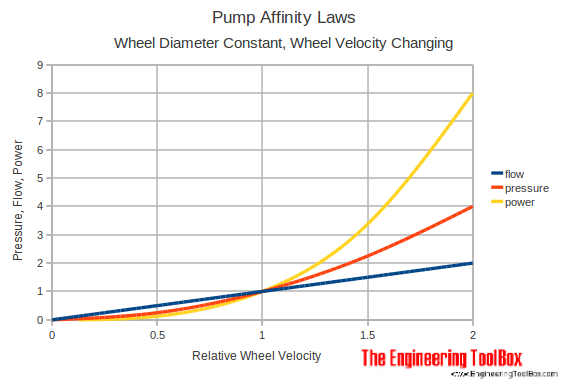
Pump Affinity Laws - Speed Variation
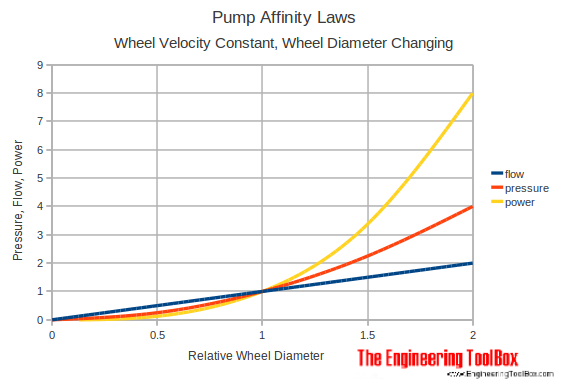
Pump Affinity Laws - Impeller Diameter Variation
Restored Original Source Tables
The following tables are restored from the original source page to preserve the complete reference data.
Original Source Images
The following original source images are preserved to avoid losing visual reference material. When an image contains chart or tabular data, its extracted values are represented in the page tables, calculators, or interactive charts; remaining images are retained as visual source references.
Engineering Notes
- Affinity laws are approximate for large changes. Deviations grow as speed departs far from the original design point because system curves shift and efficiency is not perfectly preserved. A ±20% speed change is generally reliable; beyond that, verify with manufacturer curves.
- Impeller diameter laws use the ratio , not the trimmed width. Some texts distinguish (fan-law exponent) from the empirical fan-law exponent of ~1.0 for diameter variation on centrifugal pumps. The classic relationship is most accurate for small trims.
- NPSH rises with speed squared, so reducing speed often improves suction conditions, while increasing speed can push a pump into cavitation. Always check NPSH requirements at the new speed.
- Motor and VFD sizing. Because power scales with the cube of speed, small reductions in speed yield large savings. However, the motor and variable-frequency drive must still handle the full-speed power rating during startup or transient spikes.
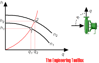
- System curve interaction. The affinity laws describe the pump curve shift; actual operating point depends on the intersection with the system curve. A speed reduction shifts the pump curve inward and downward, changing the duty point.
- Not applicable to positive-displacement pumps. These laws are derived from centrifugal pump geometry. Positive-displacement pumps follow different speed-flow relationships with near-constant flow per revolution.