
Electrical Wire Resistance and Voltage Drop
Wire resistance per unit length, voltage drop calculation, and conductor sizing.
Overview
Engineering ToolBox - Resources, Tools and Basic Information for Engineering and Design of Technical Applications!
Electrical wire resistance determines how much voltage is lost as current flows through a conductor. Selecting the correct wire gauge for a circuit depends on the allowable voltage drop, conductor material, wire length, and operating temperature. This page covers the key formulas, reference resistance values for common wire sizes, and practical design guidance.
Download and print Electrical Wire Resistance chart.
Key Formulas
Resistance of a conductor:
Voltage drop (single-phase, one-way):
Voltage drop (single-phase, round-trip):
Resistance at temperature T:
Variables
| Symbol | Description | Unit |
|---|---|---|
| R | Resistance | Ω |
| ρ | Resistivity of conductor material | Ω·m |
| L | Length of conductor | m |
| A | Cross-sectional area | m² |
| I | Current | A |
| ΔV | Voltage drop | V |
| α | Temperature coefficient of resistance | 1/°C |
| T | Operating temperature | °C |
| R₂₀ | Resistance at 20 °C | Ω |
Calculator
Wire Resistance & Voltage Drop
Conductor Resistivity
Material | Resistivity (Ω·m) | α (at 20 °C) (1/°C) |
|---|---|---|
| Copper (annealed) | 1.72e-8 | 0.00393 |
| Aluminum | 2.82e-8 | 0.00403 |
| Brass | 6.4e-8 | 0.0015 |
| Constantan | 4.9e-7 | 0.00002 |
| Gold | 2.44e-8 | 0.0034 |
| Nichrome | 0.0000011 | 0.0004 |
| Platinum | 1.06e-7 | 0.00392 |
| Silver | 1.59e-8 | 0.0038 |
| Tungsten | 5.6e-8 | 0.0045 |
| Steel | 1.43e-7 | 0.003 |
Source: engineeringtoolbox.com
AWG Wire Resistance
AWG | Area (mm²) | Resistance (Cu) (Ω/km) |
|---|---|---|
| 18 | 0.823 | 20.95 |
| 16 | 1.31 | 13.17 |
| 14 | 2.08 | 8.286 |
| 12 | 3.31 | 5.211 |
| 10 | 5.26 | 3.277 |
| 8 | 8.37 | 2.061 |
| 6 | 13.3 | 1.296 |
| 4 | 21.2 | 0.815 |
| 2 | 33.6 | 0.513 |
| 1/0 | 53.5 | 0.322 |
| 2/0 | 67.4 | 0.256 |
| 4/0 | 107 | 0.161 |
Source: engineeringtoolbox.com
Resistance vs Temperature for Copper
Copper Resistance Multiplier vs Temperature
Unit Converter
Electrical Wire Resistance Unit Converter
Interactive Wire Resistance Chart
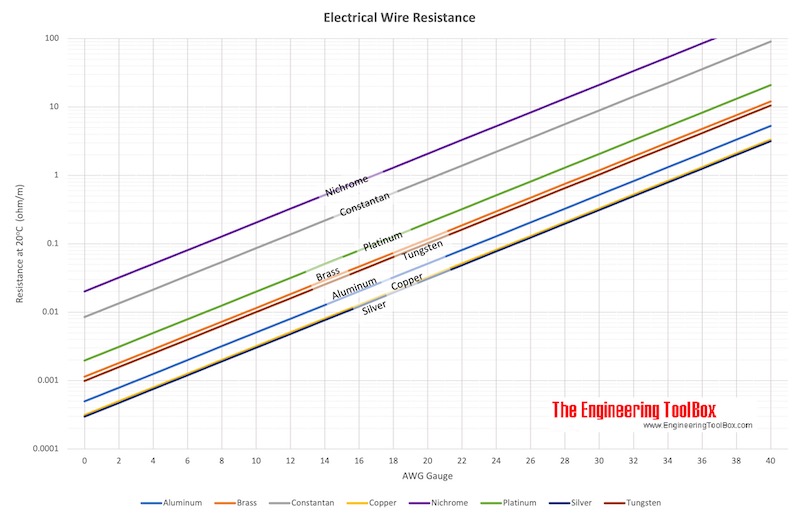
Electric Wire Resistance - AWG Gauge
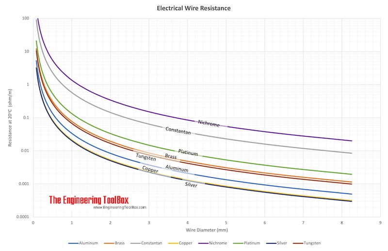
Electric Wire Resistance vs Diameter
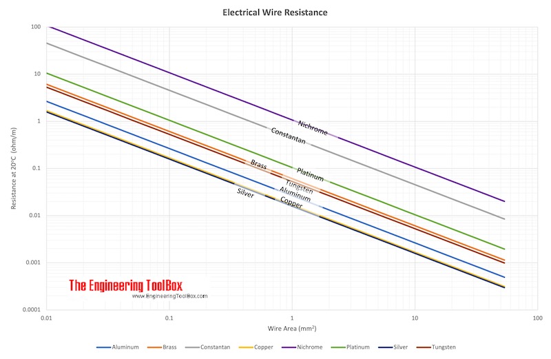
Electric Wire Resistance vs Cross-Sectional Area
Original Source Images
The following original source images are preserved to avoid losing visual reference material. When an image contains chart or tabular data, its extracted values are represented in the page tables, calculators, or interactive charts; remaining images are retained as visual source references.
Engineering Notes
- Voltage drop limits: National electrical codes commonly limit voltage drop to 3 % on branch circuits and 5 % total (feeder plus branch). Always verify local requirements.
- Temperature correction: Wire resistance increases roughly 0.4 % per °C rise for copper. At elevated operating temperatures, apply the temperature correction formula or the chart factor above.
- Aluminum vs copper: Aluminum has about 61 % the conductivity of copper, so an aluminum conductor needs roughly 1.6 times the cross-sectional area to match copper resistance.
- Skin effect: At higher frequencies, current crowds toward the conductor surface, effectively increasing resistance. The values above apply to DC or low-frequency (50/60 Hz) power distribution for solid conductors.
- Parallel conductors: When multiple conductors share a load in parallel, ensure equal lengths and terminations to avoid uneven current sharing.
- Stranded wire: Total cross-sectional area determines resistance regardless of strand count; stranded wire has the same resistance as a solid wire of equal total area.